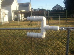
A Different way to construct a tried and true antenna out of PVC. Before you shake your head about PVC go to the PVC and sunlight study. Especially for the 10 meter and higher frequencies. By KB3TTP.
An RF choke is basicaly a current balun that divorces your antenna from the co-ax cable. This is needed to keep all your power at the antenna and stopping the co-ax from acting as a part of the antenna causing stray RF emissions. At left are the coil sizes and lengths of co-ax for various frequencies.
Here is a link to a very good method of creating this choke.
Another good option would be to construct a 1/4 wave matching section out of 75 ohm coax. this would essentially convert the 135 ohm impedence in this antenna to approx. 50 ohms, as is desired.
Take the formula that you have used on the home page to find your total wavelength for your design. Divide that by 4 and then multiply it by the velocity factor of the 75 ohm coax. This will give you the length of your matching section.
Example: This antenna is designed for 28.400 mhz with 14 ga. wire. The wavelength is 415.588 inches, divided by 4 (quarter wave) = 103.897 in. Multiplied by the velocity factor of .66 of 75 ohm coax = 65.752 Inches. This is the length of your matching section.
The picture at left shows the antenna feedpoint for an X shaped mounting which is what this antenna will be. Notice that it is the same design as for diamond shape. Also notice the two antenna wires between the stubs, ready to be soldered to the 75 ohm matching section.
The picture at left shows the wire strung through one of the spreader arms. All the wire I use in this project were purchased from "The Wireman". The antenna wire is 14 gauge Flexweave (trademark) and the coax is part #118 LO-LOSS 8X. The 75 ohm matching section described above is RG11 A/U